OPNsense WireGuard Site to Site
This article will show you how to set up an OPNsense router with a WireGuard site-to-site topology. For our example scenario, on one one side of the WireGuard connection we’ll use a generic Linux router, Router A, and on the other side, we’ll have our OPNsense router, Router B:

This connection will allow hosts in Site A (behind the Linux Router A) to connect to hosts in Site B (behind the OPNsense Router B) as if they were in adjacent LANs (Local Area Networks). In particular, we’ll allow Endpoint A (with an IP address of 192.168.1.11) in the Site A LAN (using a subnet of 192.168.1.0/24) to connect to a webserver running on Endpoint B (TCP port 80 on 192.168.200.22) in the Site B LAN (192.168.200.0/24).
Here are the steps we’ll follow:
We’ll show you how you’d accomplish each step on the Linux router first, for comparison with the OPNsense router. The steps on the Linux router will be pretty much the same as you’ll find in the WireGuard Site-to-Site Configuration guide.
Install WireGuard on Linux
To install WireGuard on Router A, install WireGuard through its OS (Operating System) package manager (as described on the WireGuard Installation page).
Install WireGuard on OPNsense
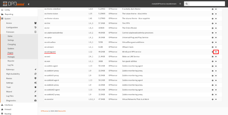
To install WireGuard on Router B, navigate to the System > Firmware > Plugins page of the OPNsense GUI (Graphical User Interface). Search for the os-wireguard package in the plugins list, and click the Add icon for it:
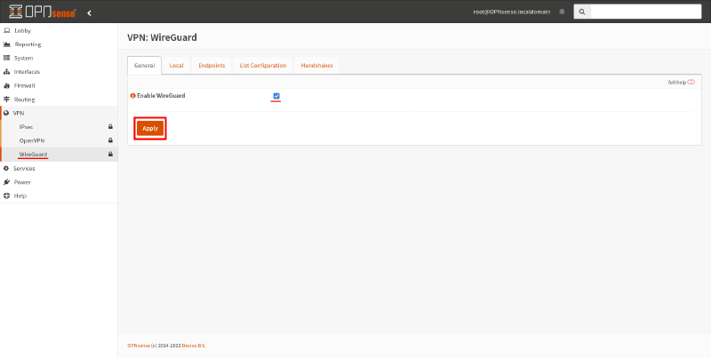
Then navigate to VPN > WireGuard page. Select the Enable WireGuard checkbox, and click the Apply button:
Configure Local Interface on Linux
First, run the following commands on Router A to generate a new WireGuard key pair for it:
$ wg genkey > router-a.key
$ wg pubkey < router-a.key > router-a.pub
This will generate two files: router-a.key and router-a.pub. The first is the private key, and the second is the public key:
$ cat router-a.key
AAAAAAAAAAAAAAAAAAAAAAAAAAAAAAAAAAAAAAAAAEE=
$ cat router-a.pub
/TOE4TKtAqVsePRVR+5AA43HkAK5DSntkOCO7nYq5xU=
Then create a WireGuard config file on Router A at /etc/wireguard/wg0.conf with the following content:
# /etc/wireguard/wg0.conf

# local settings for Router A
[Interface]
PrivateKey = AAAAAAAAAAAAAAAAAAAAAAAAAAAAAAAAAAAAAAAAAEE=
Address = 10.0.0.1
ListenPort = 51821
Be sure to replace the PrivateKey setting above with the private key you generated in the router-a.key file (and you can now delete the router-a.key file; you won’t need it again). See the Configure WireGuard section of the WireGuard Site-to-Site Configuration guide for a detailed explanation of each setting.
Configure Local Interface on OPNsense
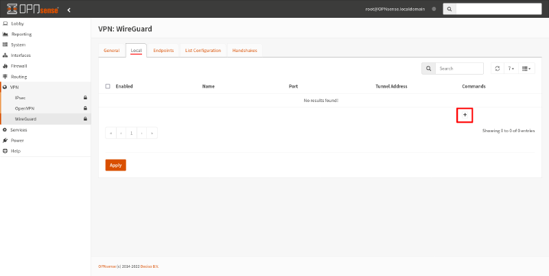
To set up a WireGuard interface on Router B, in the OPNsense GUI, switch to the Local tab of the VPN > WireGuard page. Click the Add icon this page:
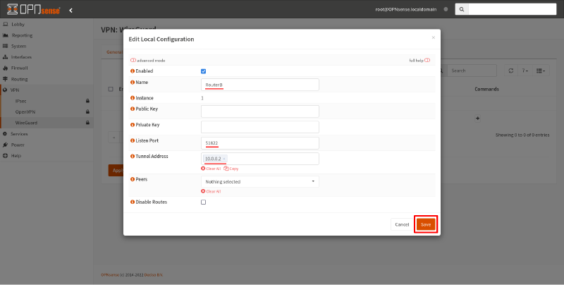
In the Edit Local Configuration dialog box, fill in the following fields:
- Name
-
Display name for the WireGuard interface, like
RouterB. - Listen Port
-
Publicly exposed UDP port on Router B to which Router A will connect, like
51822. - Tunnel Address
-
Virtual IP address of this WireGuard interface, like
10.0.0.2. Make sure this doesn’t conflict with any other networks to which Router B can connect.
Leave the Public Key and Private Key fields blank, so that OPNsense will generate a new WireGuard key pair for you. Then click the Save button:
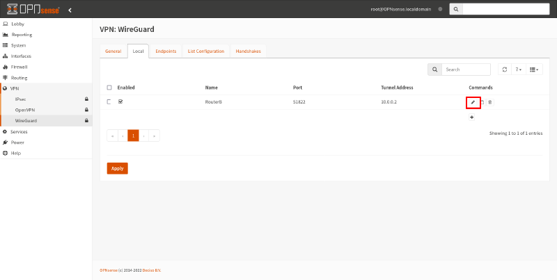
Now click the Edit icon for the WireGuard interface you just created to view the public key pair:
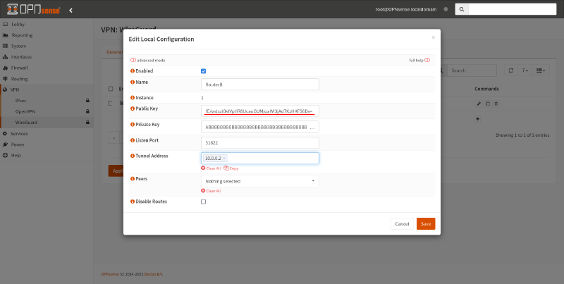
Copy the generated value from the Public Key field to Router A; you’ll need it for the next step:
|
Tip
|
If you leave the “Disable Routes” checkbox unchecked as shown in this guide, WireGuard will automatically add a route through the WireGuard interface for each network listed in the “Allowed IPs” field of the endpoints used by this interface — so you won’t have to manually make any route changes to enable access to those networks from the OPNsense LAN. If you check the “Disabled Routes” checkbox, you will have to add these routes manually. |
Configure Remote Endpoint on Linux
Back on Router A, edit the /etc/wireguard/wg0.conf file, and add the following [Peer] section to it:
# /etc/wireguard/wg0.conf

# local settings for Router A
[Interface]
PrivateKey = AAAAAAAAAAAAAAAAAAAAAAAAAAAAAAAAAAAAAAAAAEE=
Address = 10.0.0.1/32
ListenPort = 51821

# remote settings for Router B
[Peer]
PublicKey = fE/wdxzl0klVp/IR8UcaoGUMjqaWi3jAd7KzHKFS6Ds=
Endpoint = 203.0.113.2:51822
AllowedIPs = 192.168.200.0/24
Replace the PublicKey setting above with the public key you copied from Router B. Replace the Endpoint setting with the WAN (Wide Area Network) address of Router B (or the IP address of Router B from the perspective of Router A, if not the WAN address), plus the “Listen Port” setting for Router B that you chose in the step above. Include an AllowedIPs setting for each network in Site B that you want to be able to access from Site A through this WireGuard connection.
See the Configure WireGuard section of the WireGuard Site-to-Site Configuration guide for a detailed explanation of each setting.
Configure Remote Endpoint on OPNsense
To enable Router B to connect to Router A, in the OPNsense GUI, switch to the Endpoints tab of the VPN > WireGuard page. Click the Add icon on it:
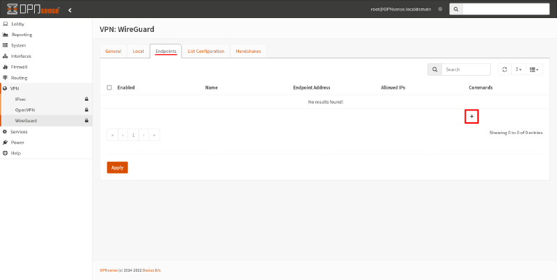
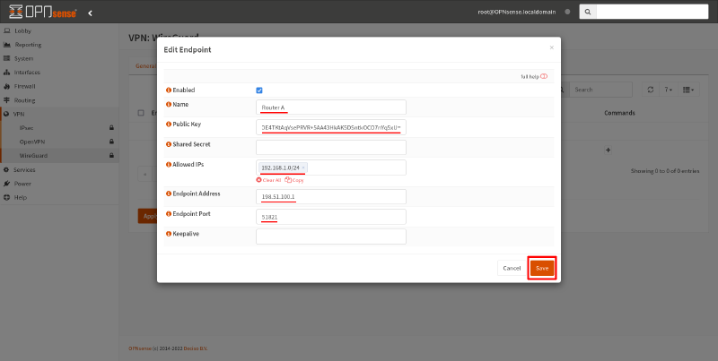
In the Edit Remote Endpoint dialog box, fill in the following fields:
- Name
-
Display name for the remote endpoint, like
RouterA. - Public Key
-
Public key you generated on Router A. Copy the content of the
router-a.pubfile you generated above and paste it into this field. - Allowed IPs
-
List of networks in Site A that you want to be able to access from Site B through this WireGuard connection. In our example, we just want to be able to access the Site A LAN,
192.168.1.0/24. - Endpoint Address
-
The WAN (Wide Area Network) address of Router A (or the IP address of Router A from the perspective of Router B, if not the WAN address). In our example, this is
198.51.100.1. - Endpoint Port
-
The “ListenPort” setting for Router A from above; in our example, this is
51821.
Then click the Save button:
|
Tip
|
If the WAN interface for Router B is itself behind NAT (Network Address Translation) — for example, the ISP (Internet Service Provider) for Site B uses CGNAT (Carrier Grade NAT) — Site A would normally be blocked from initiating connections to Site B. To work around this, you can set the Keepalive field for this endpoint to |
Next, switch back to the Local tab, and click the Edit icon for the WireGuard interface:
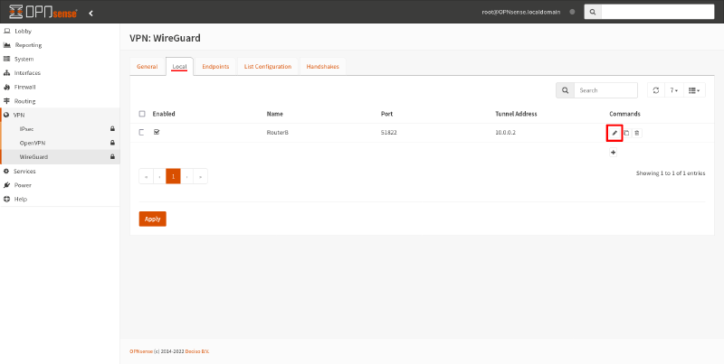
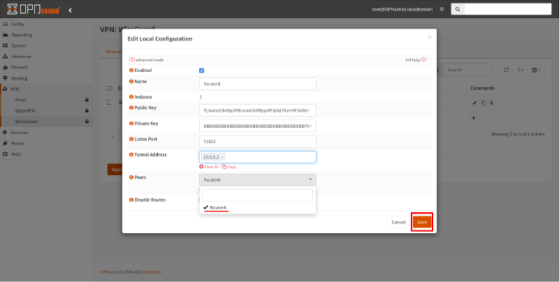
Select the endpoint you just created (RouterA) as the value of the Peers field. Then click the Save button:
Finally, to apply your changes, click the Apply button:
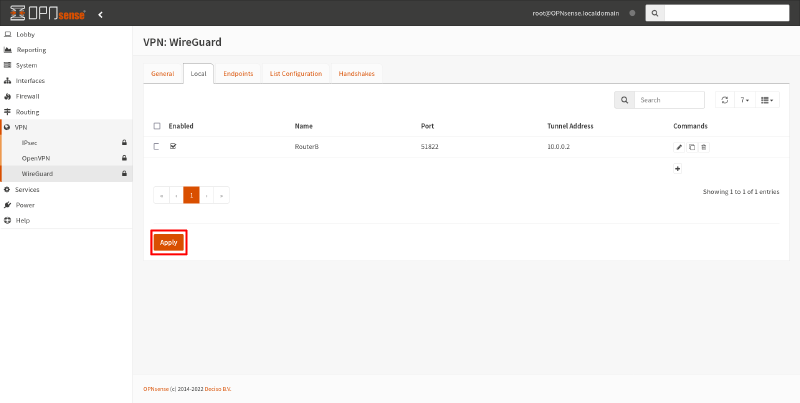
This will restart the WireGuard service on OPNsense with your new WireGuard configuration settings. You’ll need to click the Apply button (on any of the WireGuard tabs) every time you want to apply any WireGuard changes you’ve made through the GUI.
If you switch to the List Configuration tab, you’ll see the active WireGuard configuration displayed (it may take a moment for it to appear). It should look like this:
interface: wg1
  public key: fE/wdxzl0klVp/IR8UcaoGUMjqaWi3jAd7KzHKFS6Ds=
  private key: (hidden)
  listening port: 51822

peer: /TOE4TKtAqVsePRVR+5AA43HkAK5DSntkOCO7nYq5xU=
  endpoint: 198.51.100.1:51821
  allowed ips: 192.168.1.0/24
You can use this tab to check that your changes to the OPNsense WireGuard configuration has been applied.
Configure Firewall on Linux
Back on Router A, you need to make sure that your firewall allows UDP port 51821 access from Router B.
If you’re using nftables on the router, the following minimal ruleset would allow unrestricted access between Site A and Site B:
#!/usr/sbin/nft -f
flush ruleset

define wan_iface = "eth0"
define lan_iface = "eth1"
define wg_iface = "wg0"
define wg_port = 51821

table inet filter {
    chain input {
        type filter hook input priority 0; policy drop;

        # accept all loopback packets
        iif "lo" accept
        # accept all icmp/icmpv6 packets
        meta l4proto { icmp, ipv6-icmp } accept
        # accept all packets that are part of an already-established connection
        ct state vmap { invalid : drop, established : accept, related : accept }
        # drop new connections over rate limit
        ct state new limit rate over 1/second burst 10 packets drop

        # accept all DNS/NTP/DHCPv6 packets received at a link-local address
        ip6 daddr fe80::/64 udp dport { domain, ntp, dhcpv6-server, dhcpv6-client } accept
        # accept all SSH packets received on the LAN interface
        iifname $lan_iface tcp dport ssh accept
        # accept all WireGuard packets received on the WAN interface
        iifname $wan_iface udp dport $wg_port accept

        # reject with polite "port unreachable" icmp response
        reject
    }

    chain forward {
        type filter hook forward priority 0; policy drop;

        # accept all packets that are part of an already-established connection
        ct state vmap { invalid : drop, established : accept, related : accept }

        # allow all packets outbound from Site A
        iifname $lan_iface accept
        # allow all packets inbound from Site B
        iifname $wg_iface accept

        # reject with polite "host unreachable" icmp response
        reject with icmpx type host-unreachable
    }
}
table inet nat {
    chain postrouting {
        type nat hook postrouting priority 100; policy accept;
        oifname $wan_iface masquerade
    }
}
See the Site to Site section of the WireGuard With Nftables guide for an example of how to restrict inbound access to Site A from Site B through WireGuard.
Configure Firewall on OPNsense
On Router B, you usually will need to make to changes to your firewall. First, you need to add a firewall rule that allows UDP port 51822 access from Router A.
In the OPNsense GUI, navigate to the Firewall > Rules > WAN page. Click the Add icon on it:
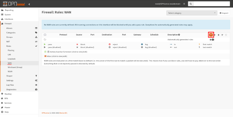
In the resulting firewall-rule edit page, set the TCP/IP Version field to IPv4/IPv6, the Protocol field to UDP, and the Destination field to WAN address. Set the Destination port range to (other) 51822:
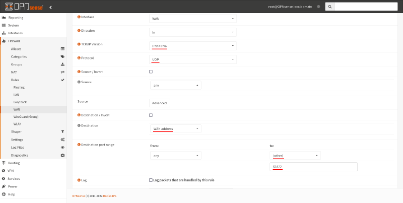
Then click the Save button on that page, and click the Apply changes button on the resulting page:
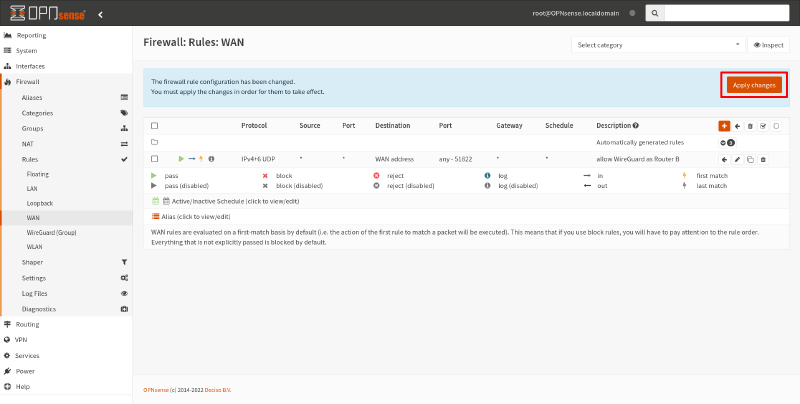
If you’re only going to use the WireGuard tunnel to connect outbound from Site B to Site A, you don’t need to make any more changes. But if you want to allow inbound connections — like we do in our example scenario, where Endpoint A in Site A initiates connections to Endpoint B in Site B — you usually will need to add additional firewall rules to allow this access.
To do this, navigate to the Firewall > Rules > WireGuard page. Click the Add icon on it:
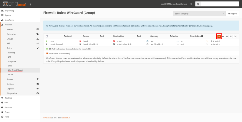
If you want to allow unrestricted inbound access from Site A to Site B, you only need to set the following fields in the resulting firewall-rule edit page:
- Source
-
Set this to the network (or networks) used by Site A. In our example, this is just
192.168.1.0/24. - Destination
-
Set this to the network (or networks) used by Site B. In our example, this is just
192.168.200.0/24.
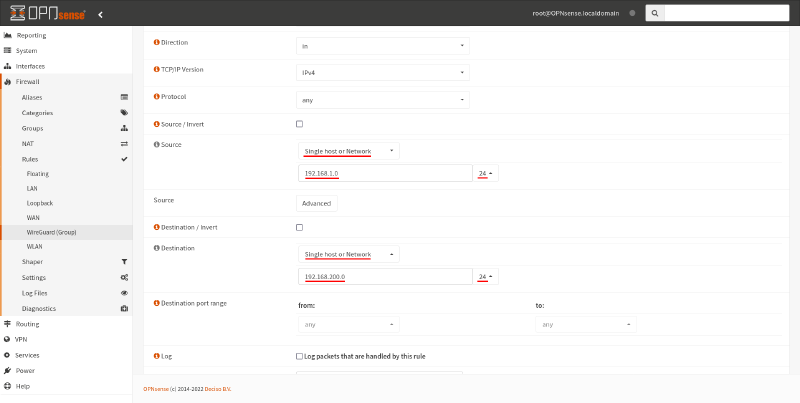
However, if you want to restrict access to allow only the single access scenario in our example, HTTP access from Endpoint A to Endpoint B, set these fields:
- Protocol
-
In our example, we’re allowing just HTTP access, so select
TCP. - Source
-
Endpoint A’s IP address on the Site A LAN is
192.168.1.11, so select this single address. - Destination
-
Endpoint B’s IP address on the Site B LAN is
192.168.200.22, so select this single address. - Destination port range
-
We’re allowing just HTTP access, so select the to
HTTPoption (port 80).
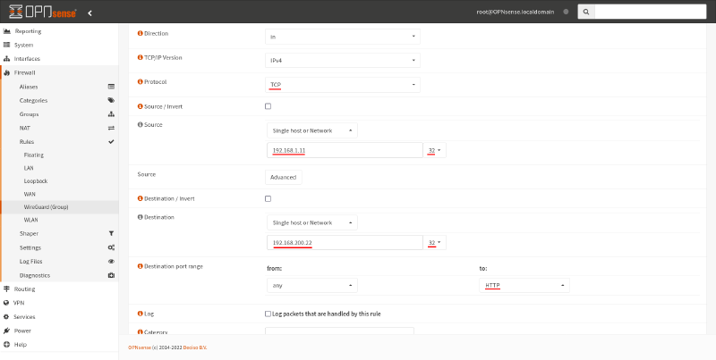
Click the Save button at the bottom of this page, and then click the Apply Changes button on the resulting page:
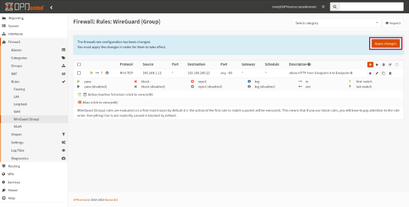
Test the Tunnel
Make sure you have a webserver on Endpoint B running on port 80. A simple substitute for a full-fledged webserver is to run Python with the http.server module:
$ sudo python3 -m http.server 80This will serve the current directory via HTTP on port 80.
On Endpoint A, try to access the webserver on Endpoint B using Endpoint B’s LAN address (192.168.200.22):
$ curl 192.168.200.22If you see any HTML output from this, then your WireGuard tunnel works!
Testing From the Routers Themselves
Note that if you try to test out connectivity by running the ping or curl commands from one of the routers themselves, it won’t work, since we haven’t included the IP address of the WireGuard interface from either router in the AllowedIPs setting of the other router.
However, assuming that the firewall rules you’ve set up on both routers allow unrestricted access between the Site A and Site B LANs, you can use each router’s own LAN address to test connectivity with the other site. (So you may want to start out with unrestricted access first, and then add more restrictive firewall rules once you know the tunnel is working.)
For example, to ping Endpoint B (192.168.200.22) from Router A (192.168.1.1), run this command:
$ ping -nc1 -I 192.168.1.1 192.168.200.22The -n flag in the above command directs ping not to try to lookup hostnames, and the -c1 flag directs it to send just 1 packet. On Linux, the -I flag specifies the local source address to use.
On FreeBSD (the OS used by OPNsense), the -S flag specifies the local source address to use; so to ping Endpoint A (192.168.1.11) from Router B (192.168.200.1), run this command:
$ ping -nc1 -S 192.168.200.1 192.168.1.11And to try to access the webserver running on Endpoint B (192.168.200.22) from Router A (192.168.1.1), run this command:
$ curl --interface 192.168.1.1 192.168.200.22If you do want to allow regular access to Site A from Router B itself, without always having to specify which source address to use, add Router B’s WireGuard address (10.0.0.2) to Router A’s AllowedIPs setting:
# /etc/wireguard/wg0.conf

# local settings for Router A
[Interface]
PrivateKey = AAAAAAAAAAAAAAAAAAAAAAAAAAAAAAAAAAAAAAAAAEE=
Address = 10.0.0.1/32
ListenPort = 51821

# remote settings for Router B
[Peer]
PublicKey = fE/wdxzl0klVp/IR8UcaoGUMjqaWi3jAd7KzHKFS6Ds=
Endpoint = 203.0.113.2:51822
AllowedIPs = 192.168.200.0/24
AllowedIPs = 10.0.0.2
And to allow regular access to Site B from Router A itself, add Router A’s WireGuard address (10.0.0.1) to the Allowed IPs setting of the endpoint for Router A on Router B:
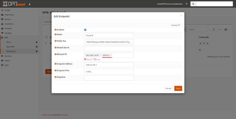
Also make sure you adjust your firewall rules to allow access from these WireGuard addresses.